
4-20 mA explained in one line: a transmitter varies the current in a loop from 4 mA (0 % of range) to 20 mA (100 %), and a receiver reads it. The signal starts at 4 mA, not 0, so a dead wire or a lost supply shows as 0 mA and cannot be mistaken for a genuine low reading. That offset is called the live zero.
Checked 28 October 2026. Facts come from four Fluke application and technical articles and the HSE pages in the sources, all opened that day. We did not find the NAMUR NE 43 text on the open web, so we do not quote its alarm levels.

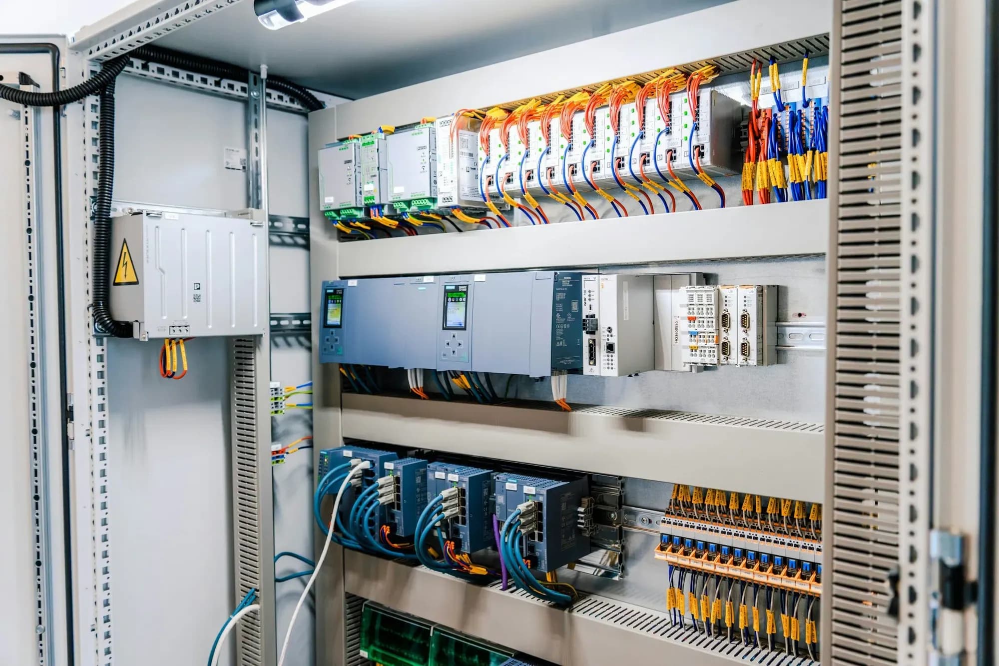
Plants like the one above carry many measurements, and many reach the control system as a 4 to 20 mA signal.
What is 4-20 mA and why does it start at 4 (live zero)?
Fluke describes the 4-20 mA loop as "the most widely used analog method" for sending measurement signals in industrial instrumentation. A transmitter turns a physical measurement, such as pressure, temperature or flow, into a proportional current. The loop usually has a power supply, a transmitter, a receiver or controller, and wiring that connects them all in series.
The live zero has a history. Fluke explains that earlier pneumatic systems used a 3 to 15 psi signal, so a real zero (3 psi) could be told apart from a failure (0 psi). Current signals took over in the 1950s and kept the same idea at 4 mA. In Fluke's words, the live zero "allows detection of faults like broken wires (which would read 0 mA)".
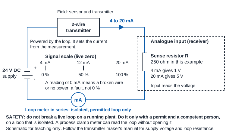
The diagram shows the loop in our own simplified drawing, with the loop meter in the bottom wire. The scale is linear, so:
| Loop current | Percent of range | Meaning |
|---|---|---|
| 0 mA | not a valid reading | Open circuit or no power (a fault) |
| 4 mA | 0 % | Bottom of the range |
| 8 mA | 25 % | |
| 12 mA | 50 % | Middle of the range |
| 16 mA | 75 % | |
| 20 mA | 100 % | Top of the range |
Fluke's guide uses the same 25 % steps to check linearity. The span is 16 mA.
How does a loop-powered transmitter work?
A two-wire transmitter takes its power from the loop and sends its signal on the same pair. Fluke describes this: a single twisted-pair cable supplies power to the transmitter and also carries the output signal. The transmitter regulates the current, and that same current flows through every device in the series loop.
Fluke's loop description names these parts:
- Power supply. Usually 24 V DC. Fluke notes that 9, 12 and 24 V loops are also common, so check the one you have.
- Transmitter. Converts the measurement to a proportional current.
- Receiver. A PLC, DCS or display that interprets the current.
- Load (sense) resistor. Optional, converting the current to a voltage for an analogue input. Fluke says 250 to 500 ohm resistors are common.
- Wiring. Connects them in series.
The current is the same everywhere in a series loop. The supply must provide enough voltage to push the current through the cable and all the devices. Fluke's FAQ states that if the loop resistance is too high, the transmitter may not be able to maintain the correct current, giving inaccurate readings or failure. The supply voltage and maximum loop resistance for a device are in its manual: use those, not a rule of thumb.
Scaling: mA to engineering units, a worked example and the PLC step
The scale is a straight line, so the maths is a ratio. For a pressure transmitter ranged 0 to 10 bar:
- Engineering value = low range + (mA - 4) / 16 x (high range - low range)
- At 12 mA: 0 + (12 - 4) / 16 x 10 = 5 bar.
- At 7.2 mA: 0 + (7.2 - 4) / 16 x 10 = 2 bar.
- At 20 mA: 10 bar.
Fluke's guide gives the same check from the other direction: with 4 mA simulated, the controller should indicate the 0 % value of the transmitter, and with 20 mA the 100 % value.
If the input uses a 250 ohm sense resistor, as in Fluke's example, Ohm's law gives the voltage the input sees: 4 mA gives 1 V and 20 mA gives 5 V. Fluke's calibration guide describes this 1 to 5 V arrangement with a 250 ohm resistor.
In a PLC, an analogue input card turns that voltage or current into a raw count. The programme then scales the count to engineering units with the same linear formula. The raw counts for 4 mA and 20 mA are in the card's manual. Check them there, because they differ by manufacturer and range. Good scaling logic also tests for a value below the live zero and raises a wire-break alarm.
For error, Fluke gives the formula (nominal - actual) / span x 100, with the span as 16 mA. Its example: if 0 % applied indicates 1 %, the error is 0.0625, or 6.25 % of span, so adjustment may be needed.
2-wire, 3-wire and 4-wire devices, and where does HART sit?
The pages we opened describe the two-wire loop above: power and signal on one pair. They did not describe three-wire and four-wire devices in enough detail to quote. In general those devices have separate power connections, but the wiring differs by maker, so use the device manual and its terminal diagram, and treat our general description as a prompt to check, not a source.
HART is a digital protocol that rides on the 4 to 20 mA signal. Fluke says the 4-20 mA signal carries no device diagnostics or metadata unless it is paired with a digital protocol such as HART, and that HART can overlay digital data on the analogue signal. The FieldComm Group page for HART blocked our automated check, so we have not quoted its specification. If you meet HART, remember the analogue part still works the same way.
How do you do a loop check, step by step (safety first)?
A loop check proves that the signal travels correctly from the field device to the control system. Fluke says a full verification includes testing the transmitter output, the wiring, the input to the control system and the input card, and the return wiring to the transmitter.
- Permit and agree the plan. Fluke's own method for a multimeter starts with "check with operations before initiating the measurement". Agree what will happen to the control system when the loop is opened, and put the controller in a safe state if the plan needs it.
- Isolate. Make the loop safe to work on as the site's isolation procedure requires. Do not open a loop that is still live and running the plant.
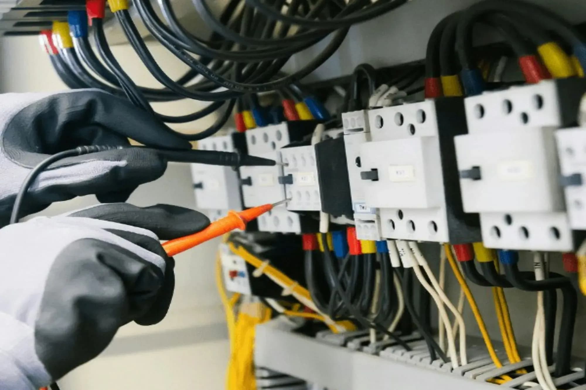
- Choose the method. A process clamp meter reads the loop without breaking it: Fluke's method is to access the signal wires, zero the clamp, and check the reading is between 4 and 20 mA. A multimeter or loop calibrator in series does interrupt the loop: you disconnect one lead of the signal wire and put the meter in series.
- Meter in series on an isolated, permitted loop. Select the mA DC function and connect the test leads for mA measurement. Mind the meter's current range and fuse: the second video covers blowing the fuse.
- Simulate. Fluke's "mA simulate" mode lets a loop calibrator stand in for the transmitter, drawing power from the 24 V loop supply. Set 4 mA, and the HMI or controller should read the 0 % value. Set 20 mA, and it should read 100 %. Check 12 mA for 50 %.
- Record. Write down the loop tag, the points tested (for example 4, 12 and 20 mA), the readings and any deviation. Fluke gives the error formula above for comparing results with the tolerance.
- Restore. Reconnect, remove the meter, check the signal is back to the process value, tell operations and close the permit.
A short video shows the ideas. The first, from Instrumentation Tools (uploaded 3 December 2020), covers the history and pros and cons of the 4-20 mA loop. The second, by Tim Wilborne (7 February 2024), shows how to measure a 4-20 mA circuit without blowing the meter's fuse. Both are general and not UK specific, so follow your site's isolation rules over anything on screen.
Fault finding: 0 mA, a low reading, a high reading and a drifting reading
| Symptom | What it points to | Check |
|---|---|---|
| 0 mA | Open circuit or no power. Fluke says a broken wire reads 0 mA | Loop supply voltage, fuses, terminations, the transmitter |
| Below 4 mA but not zero | A fault or alarm state, depending on the device | The device manual |
| Above 20 mA | The device is out of range or in an alarm state, depending on the device | The device manual |
| Reading drifts or wanders | Loose termination, a noisy or damaged cable, or a failing transmitter | Terminations, the transmitter output with a simulate test |
We can only quote what the pages we opened say. Fluke's mA simulate article gives this fault-finding sequence: if no value shows or the calibrator shows an open circuit, check the input card, its fuse and the 24 V loop supply. Measuring the voltage at the disconnected transmitter wires should show the full 24 V. If simulating a good signal makes the loop work, the fault is likely the transmitter or its sensor. Fluke also describes testing a card input fuse by continuity, with a value of between 100 and 250 ohm. These are Fluke's figures for its example, so use your system's documentation.
Some devices drive their output below 4 mA or above 20 mA to flag a fault. The levels used for that are set out in the NAMUR NE 43 recommendation, which we could not read. We therefore do not state any levels: look at the transmitter manual for the values it uses, and at your control system's configuration for how it treats out-of-range signals.
Where does a loop check fit in a commissioning job?
On a commissioning job, each instrument loop is checked from field to control system before the plant runs: the right tag, the right range, the right engineering units, the right alarm. The documents that define this are the P&ID, the loop diagram and the instrument datasheet. The loop check records that the number on the screen matches what the instrument sees. A free course covers the full sequence, instrument calibration, loop checks and commissioning.
For the background, read how to read instrumentation design documents and our guide to industrial sensors. You can see what UK employers ask for on the instrument technician jobs page.
Practise loop checks free
You can practise the reading and the sums safely on screen before you ever meet a live loop. The multimeter simulator lets you practise range settings and series versus parallel connection, and the process control simulator shows how a process variable and its signal behave in a loop. Our free industrial instrumentation course covers the transmitters themselves.
Start free
- Free industrial instrumentation course: sensors, transmitters and signals.
- Instrument calibration, loop checks and commissioning: the full method.
- Multimeter simulator and process control simulator: practise on screen.
- Instrument technician jobs: read real adverts.
Job simulations are practice, not employment, and certificates are certificates of completion, not regulated qualifications. Nothing here promises a job, and no simulator replaces a permit and a competent person on a real plant. For the law and guidance on safe electrical work, see HSE electrical safety. If you are weighing instrumentation as a career, read our instrument technician guide.